Наші генератори розроблені як IT-системи та мають базовий захист завдяки основній ізоляції живих компонентів. Це захисне розділення. Контакти PE в розетках, а також заземлювальний гвинт, з'єднані з корпусом генератора. Корпус генератора ізольований від живих ліній L і N.
Аварійні джерела живлення в будівлях зазвичай повинні бути встановлені як система TN. У цьому випадку генератор і його нейтральний провідник повинні бути заземлені. Гвинт заземлення генератора повинен бути підключений до головної заземлювальної шини будівлі за допомогою мідного кабелю перерізом 6-10 мм². Якщо це відсутнє, для генератора повинна бути встановлена система заземлення. Провід PE від розетки генератора йде до гвинта заземлення в розподільчій коробці, який, у свою чергу, повинен бути підключений до головної заземлювальної шини. Провід N від розетки генератора повинен бути заземлений у точці підключення в розподільчій коробці. Це можна зробити, встановивши місток між N і PE на стороні генератора перемикача передачі.
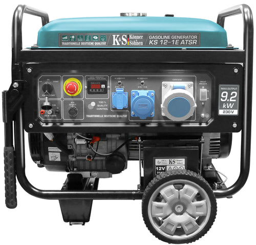
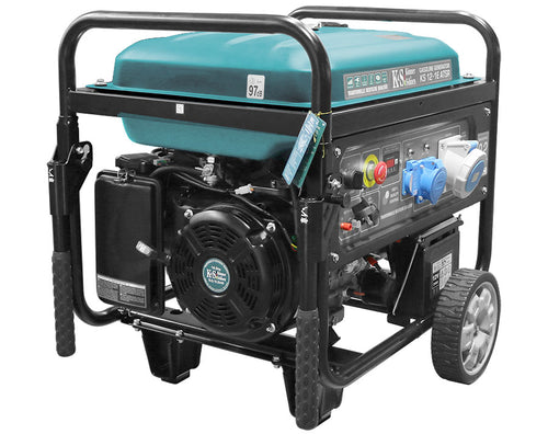
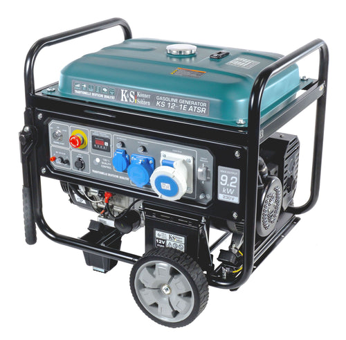
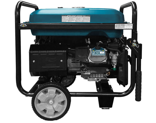
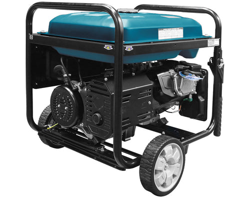
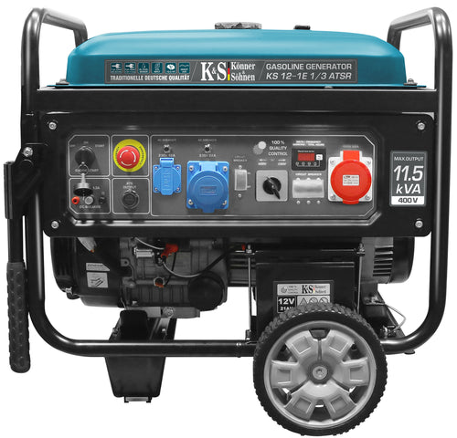
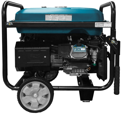
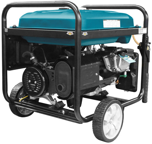
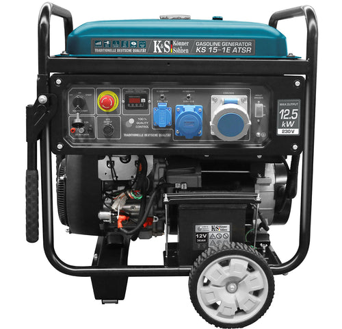
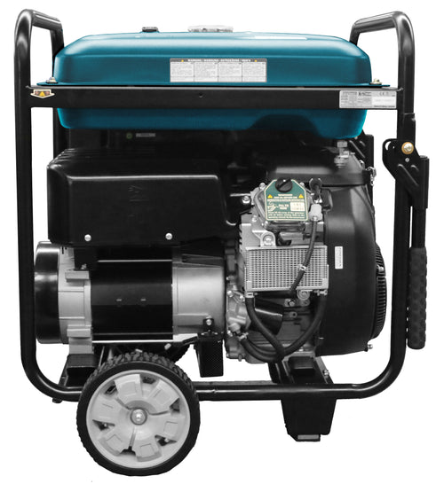
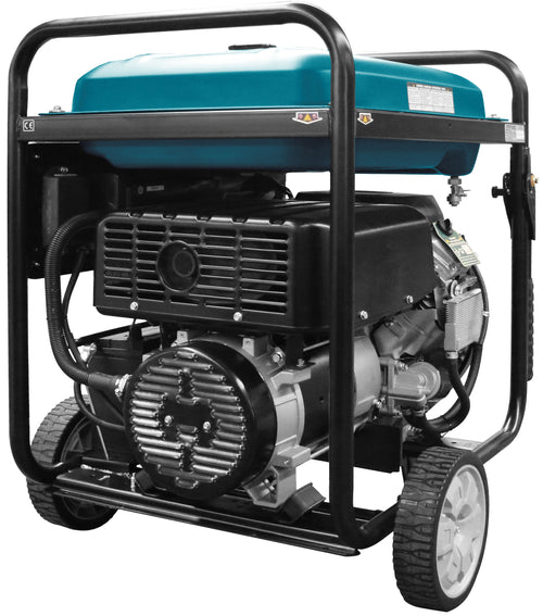
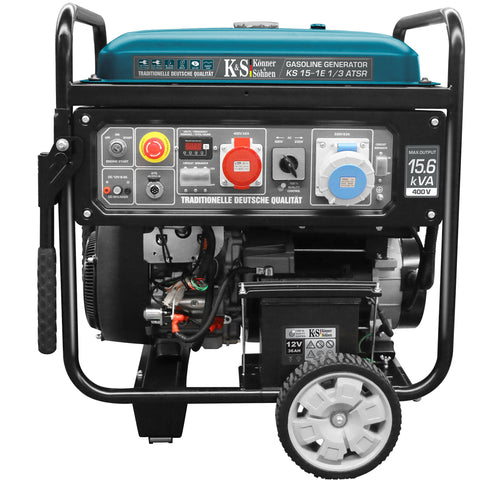
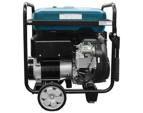
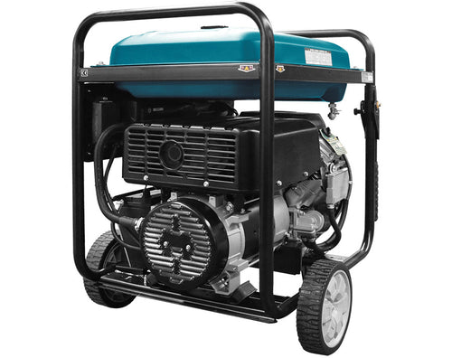
Моделі KS 12-1E ATSR, KS 12-1E 1/3 ATSR, KS 15-1E ATSR, KS 15-1E 1/3 ATSR забезпечують 230В і можуть використовуватися як аварійне джерело живлення для споживачів електроенергії на 230В.
Хоча трифазна електрична плита підключена до трьох фаз, зазвичай вона є споживачем потужності 230В, з розподілом нагрівальних елементів на три групи для розподілу навантаження. Її можна живити від однієї фази 230В від генератора. Однак не всі зони приготування та духовка можуть бути активовані одночасно, щоб уникнути перевантаження нейтрального проводу до електричної плити від розподільчої коробки.
Ось рекомендований план підключення для живлення будинку відповідно до керівництва VDN з планування, будівництва та експлуатації систем з аварійними генераторами для моделей 230В та 1/3 моделей з VTS у режимі 230В:

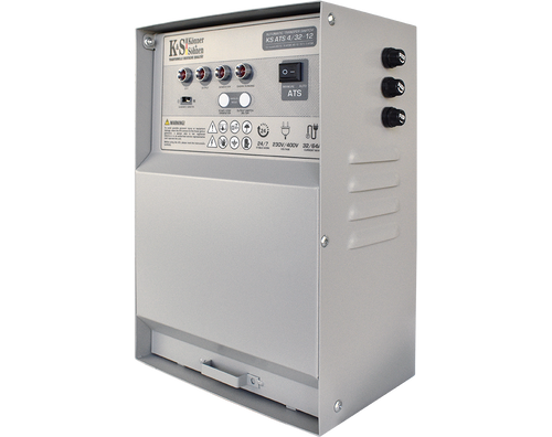
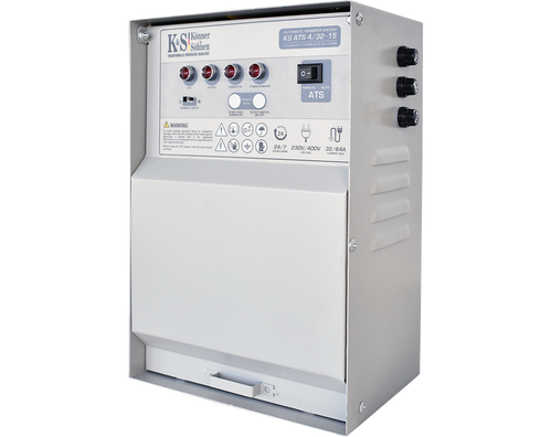
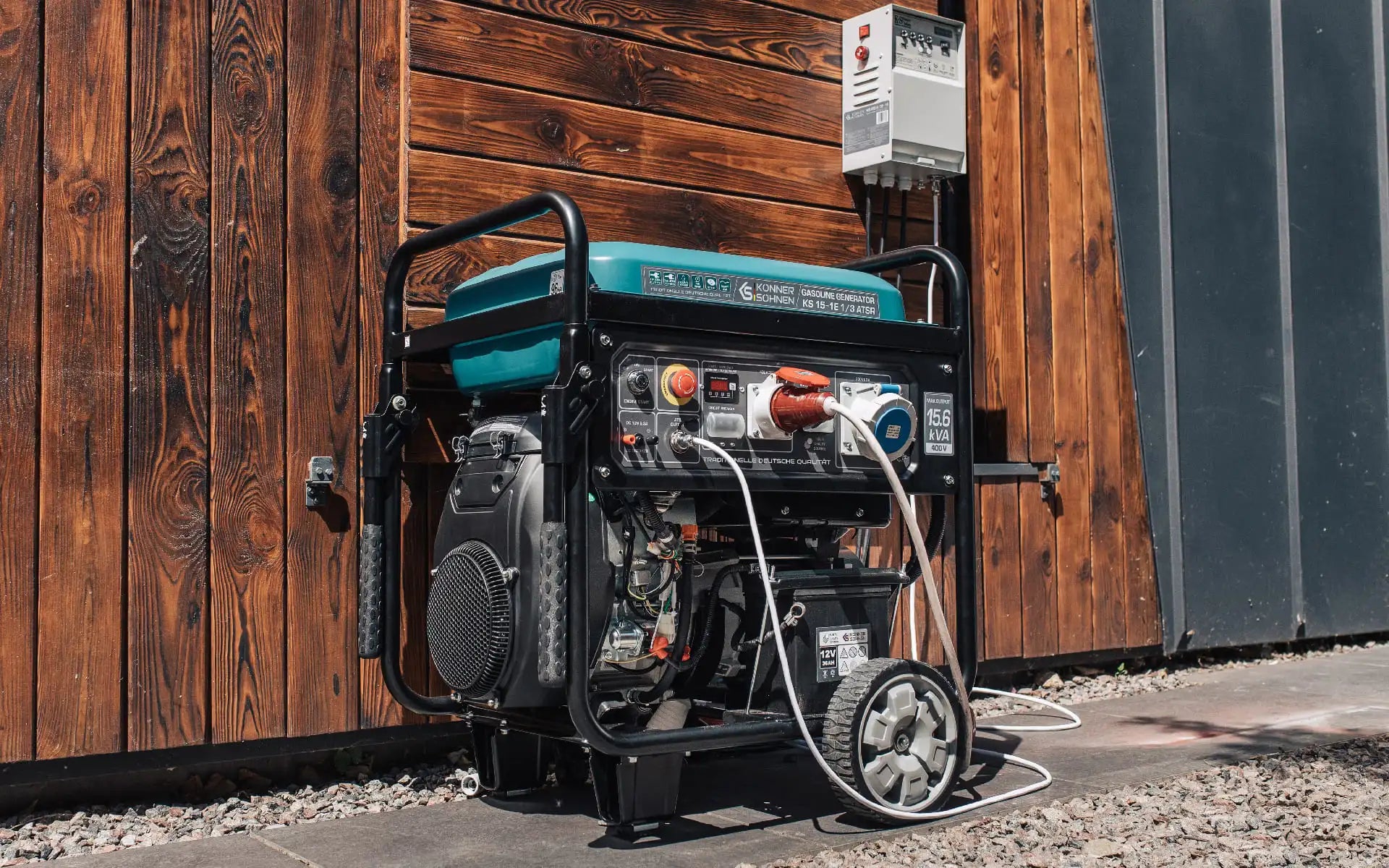
Генератори серії KS 12 та KS 15 мають підключення ATS і можуть працювати автоматично з зовнішнім блоком ATS.
Коробка KS ATS 4/32-12 призначена для моделей KS 12-1E ATSR та KS 12-1E 1/3 ATSR.
Коробка KS ATS 4/32-15 призначена для моделей KS 15-1E ATSR та KS 15-1E 1/3 ATSR.
Ці АВР-бокси оснащені контакторами з комутаційними контактами на 32А.
Рекомендований план підключення для однофазної електромережі:

Рекомендований план підключення для трифазної електромережі (до 32А споживання струму):

Рекомендований план підключення для трифазної електромережі (споживання струму понад 32А):

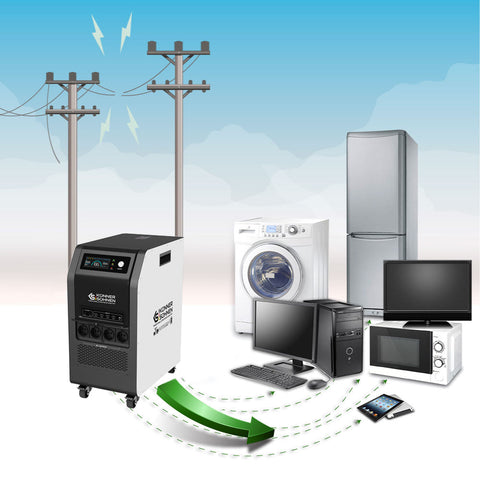
У цій схемі споживачі електроенергії поділяються на тих, хто має постійний доступ до аварійного живлення, і тих, кого можна підключити (високопродуктивні прилади, такі як електричні плити). Це стосується виключно споживачів електроенергії на 230В, навіть якщо вони живляться від трифазної зовнішньої електромережі під час нормальної роботи.
Трифазний струм 400В потрібен лише для пристроїв, які вимагають обертового поля. Це споживачі енергії з трифазними двигунами, такі як інструменти, насоси тощо.
Споживачі електроенергії, такі як електричні плити, потужні проточні водонагрівачі, тепловентилятори, електричні котли та сауни, підключаються до трифазного струму виключно з метою розподілу навантаження в мережі VDN і, фактично, є споживачами потужності 230В, які можуть бути забезпечені генератором на 230В.
Споживачі потужності 230В із загальною потужністю понад 4,6 кВА повинні бути підключені до 3 фаз для розподілу навантаження при роботі від зовнішньої електромережі. У режимі аварійного живлення, при використанні аварійного генератора з несиметричним навантаженням, вони повинні отримувати 230В, але не повинні бути доведені до повної потужності, щоб уникнути перевантаження нейтрального провідника.
Споживачі електроенергії, такі як електричні плити, зазвичай підключаються за допомогою мідного кабелю 5 x 2,5 мм². Таким чином, при живленні від генератора, пара варильних поверхонь або варильна поверхня та електрична духовка можуть працювати без проблем, не перевантажуючи нейтральний провід живильного кабелю. За умови, що сам генератор має достатню потужність. Те ж саме стосується проточних водонагрівачів, тепловентиляторів, електричних бойлерів, саун тощо, які мають внутрішні нагрівальні елементи на 230В і, фактично, є споживачами електроенергії на 230В.
ATS контролює напругу на стороні "Міська електромережа" фази А і автоматично запускає генератор у режимі "Авто", як тільки напруга зникає. Після запуску генератора перевіряється його напруга, і живлення споживачів, які мають право на аварійне живлення, перемикається на генератор. Мережа відключається по всіх полюсах. Коли напруга повертається на сторону "Міська електромережа", "Вихід навантаження" перемикається на сторону "Міська електромережа", і генератор зупиняється.
Блок живлення, вбудований в ATS, також підтримує акумулятор генератора, щоб він завжди залишався готовим до використання, і в разі відключення електроенергії живлення 12В бере на себе.
Кабель керування ATS також може бути подовжений. Рекомендований переріз становить 1,5 мм² на провід.
Моделі KS 12-1E 1/3 ATSR та KS 15-1E 1/3 ATSR з системою VTS можуть використовуватися для аварійного електропостачання як споживачів електроенергії на 230В, так і на 400В, не одночасно, а почергово та без автоматичної роботи. Режим 400В призначений виключно для споживачів електроенергії на 400В, які потребують обертового поля.

Резистивне навантаження 100-200 Вт (наприклад, 2 x 100W лампи розжарювання або ІЧ-лампи) служать для балансування нелінійних малопотужних споживачів електроенергії, присутніх у домогосподарстві, таких як маршрутизатори, супутникові перемикачі, зарядні пристрої для мобільних телефонів, світлодіодне освітлення тощо, які споживають лише частину синусоїди і таким чином спотворюють напругу. Важливо уникати гармонік, шкідливих для споживачів електроенергії, коли такі споживачі є єдиними активними в будинку.
Резистивне балансувальне навантаження навантажує частини синусоїди напруги, які не навантажуються нелінійними електронними споживачами енергії, і таким чином зменшує гармоніки.
Напруга (жовта) та струм (зелений) звичайного генератора під електронним навантаженням без і з балансувальним навантаженням (лампа на 100 Вт):


Ви можете побачити, що збурюючі гармоніки, позначені червоними стрілками на лівому зображенні, значно менші на правому зображенні, і більшість електронних модулів тоді функціонують без проблем.
У звичайних генераторах (включаючи ті, що з AVR), струм береться з обмотки альтернатора, і форма напруги може відхилятися від синусоїдальної хвилі в залежності від конструкції генератора та підключених споживачів енергії. Частота напруги звичайного синхронного генератора визначається швидкістю двигуна, яка може коливатися в залежності від навантаження. Допустиме значення становить 50-53 Гц і знаходиться в межах допустимого діапазону.
Ви повинні звернутися до виробника відповідного пристрою, щоб дізнатися, чи дозволено вам живити ваші чутливі пристрої за допомогою звичайного генератора, оскільки це залежить виключно від конструкції пристрою та його реакції на форму напруги, яка відрізняється від синусоїдальної.
Для аварійного електропостачання без АВР генератор повинен запускатися з вимкненим автоматичним вимикачем (на генераторі). Потім необхідно перевірити напругу генератора, і лише коли рівень напруги та частота (50-53 Гц) є правильними, слід підняти автоматичний вимикач і підключити навантаження. Перед зупинкою генератора навантаження спочатку повинно бути деактивовано за допомогою автоматичного вимикача на генераторі, і лише потім генератор слід зупинити, щоб запобігти пошкодженню споживачів електроенергії та самого генератора через перехідні процеси. При переключенні з режиму 230В на 400В і навпаки, навантаження спочатку повинно бути деактивовано, режим повинен бути змінений, і напруга повинна бути перевірена. Лише після цього навантаження слід активувати за допомогою відповідного автоматичного вимикача.
Моделі KS 12-1E 1/3 ATSR та KS 15-1E 1/3 ATSR також можуть працювати автоматично як чисті генератори на 400В для трифазних споживачів (без повного підключення до будинку):

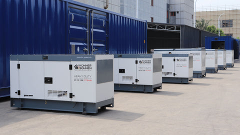
Наші генератори є аварійними джерелами живлення і не підходять для безперервної, безперебійної роботи.
Ми рекомендуємо використовувати всі наші бензинові генератори до 5 годин, але потім робити перерву на 30-60 хвилин для охолодження.
Відмова від відповідальності:
Цей посібник призначений лише як керівництво, є ілюстративним і має бути адаптований до конкретних обставин і умов на місці під час встановлення. Саме встановлення повинно здійснюватися у відповідності з усіма стандартами та нормами. Ми не несемо відповідальності за неправильні встановлення та їх наслідки.