Generators of the above-mentioned series are designed as mobile power generators in an IT system and feature basic protection through basic insulation of the live parts. The PE pins in the sockets, as well as the grounding screw, are connected to the body of the generator. Active L and N lines are stripped from the generator housing.
Emergency power supply in buildings must generally be implemented as a TN system. In this case, a TN system must be constructed with the generator. The generator itself and its neutral conductor must be grounded.
More information can be found in our information material "TN system for home supply with emergency power generators".
Generators with Schuko sockets and CEE sockets with a 6h PE position are designed as IT systems for mobile use, but can generally also be used for household power supply. The power cable between the generator and the transfer switch can be considered a generator outgoing line, via which the generator's neutral conductor can be grounded. The generator itself may not be converted; it remains an IT system and can be used mobile if necessary, but becomes part of the TN system once it is connected to the house. The exception to this is permanently installed generators.
The generator (housing) must be grounded either via the building's grounding system or via a grounding system specifically designed for the generator (earth spike, cross-grounding system). The generator is grounded via the grounding screw. The PE conductor of the power cable alone is not sufficient to ensure reliable grounding of the generator.
The grounding screw on the generator must be connected to the main grounding bar in the house using a 6-10 mm² copper cable. If this is missing, a grounding system must be installed for the generator. The PE conductor from the generator socket goes to the grounding screw in the distribution box, which in turn must be connected to the main grounding bar. The N conductor from the generator socket must be grounded at the connection point in the distribution box. This is done by placing a jumper between N and PE on the generator side of the transfer switch.
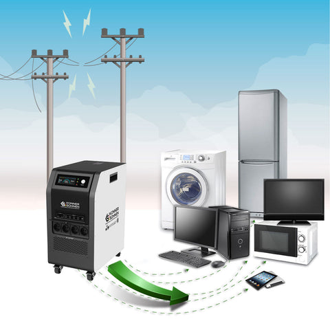
Models of the KS 2900, KS 3000, KS 3900, KS 5000 series supply 230V and can be used as an emergency power source for 230V power consumers.
A 3-phase electric stove is connected to three phases, but is usually a 230V power consumer, with heating elements divided into three groups for load distribution. It can be powered by a single 230V phase of the generator. However, it is important to ensure that the total activated power of the heating elements does not exceed 1/3 of the connected load to avoid overloading the neutral conductor.
More information regarding 230V and 400V home supply can be found in our information material on the topic of "Emergency power generator 230V or 400V".
It is essential to pay attention to the total current consumption of the active power consumers so that the generator or its Schuko socket (max. 16A) is not overloaded.
Here is the recommended connection plan for a house feed-in according to the VDN guideline for the planning, construction and operation of systems with emergency power generators:

The Schuko plug can be reversed on the generator without affecting the phase and neutral in the house, as the two current-conducting contacts in the Schuko socket are equivalent as long as neither is grounded. The generator's circuit breaker will trip in the event of a short circuit in the power consumer (L to PE) in either position of the Schuko plug, as N and PE are bridged externally.
The second, free Schuko socket (models with 2 Schuko sockets) receives the earthed neutral conductor immediately after plugging the cable to the changeover switch into the first socket, since the two Schuko sockets are connected in parallel.

Emergency power for house with 230V feed-in socket on the outside wall :

This connection option has many advantages. A transfer switch is installed in the house's distribution board, and a TN system is constructed on the generator side (bridge between N and PE). In the event of a short circuit (L against the power consumer housing), the current flows via the bridge from PE to N, and the miniature circuit breaker on the generator trips. The generator's grounding screw must be connected either to the house's ground via the pre-installed fixed grounding point or to a specially constructed grounding system. The generator can be connected to the feed-in box using a standard extension cable (suitable for the socket type). No permanent installation is required; the generator is only used in the event of a power outage and can be connected at any time without great effort.
We recommend using a copper cable with a cross-section of 4-6 mm² per wire between the feed-in box and the changeover switch, so that you have the option of connecting a more powerful generator in the future.
The generator is started and the voltage is checked before connecting the load. The frequency of a conventional synchronous generator is controlled by the engine speed and can be in the range of 50 to 53 Hz. This can be adjusted if necessary using the adjusting screw (the spring-loaded adjusting screw above the carburetor).
Then, use the transfer switch to transfer the house's power supply to the emergency generator. When power from the public grid returns, transfer the transfer switch to the public grid. The generator may be stopped.
The 100-200W base load (e.g., 2 x 100W incandescent or IR light bulbs) serves to balance the nonlinear small power consumers present in a household, such as routers, satellite switches, cell phone chargers, LED lighting, etc., which consume only a portion of the sine wave and thus distort the voltage. It is important to avoid harmonics harmful to the power consumers when such power consumers are the only ones active in the home.
The resistive balancing load loads the parts of the voltage sine wave that are not loaded by non-linear electronic power consumers and thereby dampens the harmonics.
You can find more information on this topic in our information material regarding power generators and electronic power consumers.
Voltage (yellow) and current (green) of a conventional generator under electronic load without and with balancing load (100W light bulb):


You can see that the disturbing harmonics marked with the red arrows in the left image are much smaller in the right image and most electronic modules then function without problems.
In conventional generators (including those with AVR), the current is taken from the alternator winding, and the voltage waveform may deviate from a sine wave depending on the generator design and connected power consumers. The voltage frequency of a conventional synchronous generator is determined by the motor speed, which can fluctuate depending on the load. A value of 50-53 Hz is permissible and within the tolerance range.
You must ask the manufacturer of the respective device whether you are allowed to power your sensitive devices with a conventional generator, as this may depend solely on the design of the device.
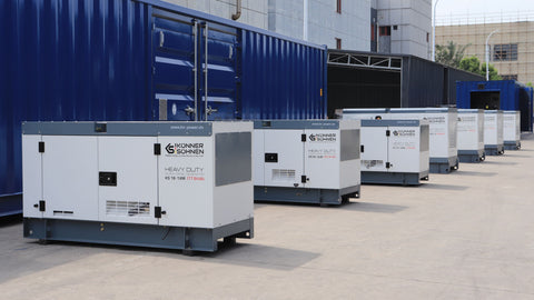
The generators described in this article are emergency power generators and are not suitable for continuous operation. We recommend running all of our gasoline generators for up to 5-6 hours (depending on load and outside temperature), but then taking a 30-60 minute break to cool down.
Disclaimer:
This manual is intended only as a guide, is illustrative, and must be adapted to the specific circumstances and conditions on site during installation. The installation itself must be carried out in compliance with all standards and regulations. We assume no responsibility for incorrect installations and their consequences.